
EECE 5550 Mobile Robotics
Lecture 3
Kinematics and Motion Models
Dr. Xian Li
Department of Electrical and Computer Engineering
Northeastern University
EECE 5550 Mobile Robotics
2
Today
The model your robot actually runs.
● What a model is for, and what it leaves out
● The simplest models: integrators
● The unicycle, and the constraint that defines it
● Differential drive, derived
Reading
Lynch & Park, Modern Robotics
●Ch. 13.1 to 13.3, wheeled mobile robots
Siegwart et al., Autonomous Mobile Robots
●Ch. 3, Mobile Robot Kinematics
Lecture 2 covered where things are. This one covers how they move.
One question, all lecture
You command 0.3 m/s forward for 4 seconds. Where are you?
Three different numbers. By the end you will know which to trust, and for what.
EECE 5550 Mobile Robotics
●Sense: Process sensor data to construct a model of the world
●Think: Construct a plan to move from the current state to the goal state
●Act: Control actuators to execute plan
Sense → Think → Act
Next: Basic models of robot motion
Recap: The Central Dogma of Robotics
4
EECE 5550 Mobile Robotics
5
Modeling
Mathematical: describing important system characteristics via equations
●For example, applying laws of physics to model a physical system
Models may involve unknown parameters, estimated from experiments
When well-established laws are not available, empirical data is used
●Input and output relationships based on data
EECE 5550 Mobile Robotics
6
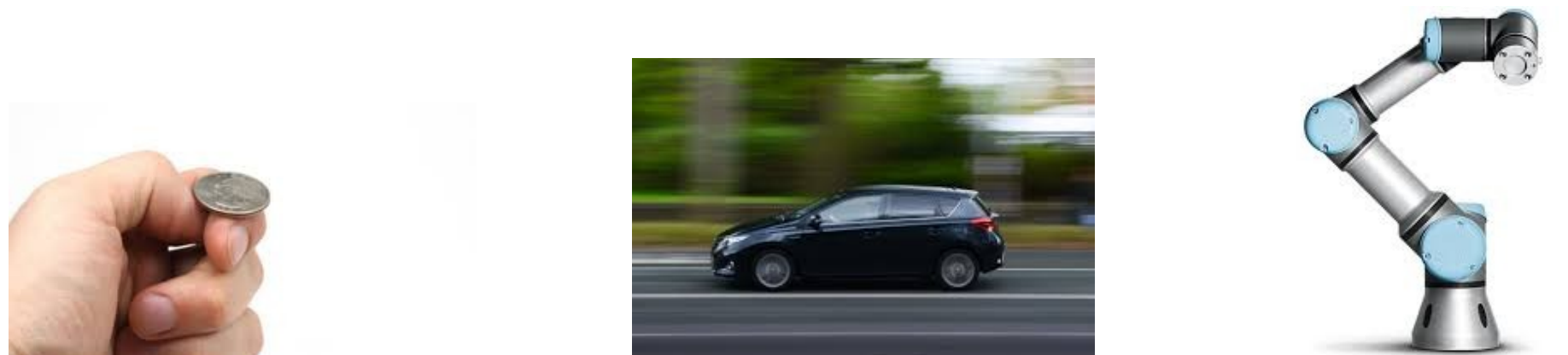
Simplicity against accuracy
Models with higher accuracy are usually more complicated to use and analyze
●A compromise has to be made between simplicity and accuracy
●Which aspects are negligible, and which are essential for the task at hand?
All models are flawed, but some are very useful.
EECE 5550 Mobile Robotics
7
Robot motion
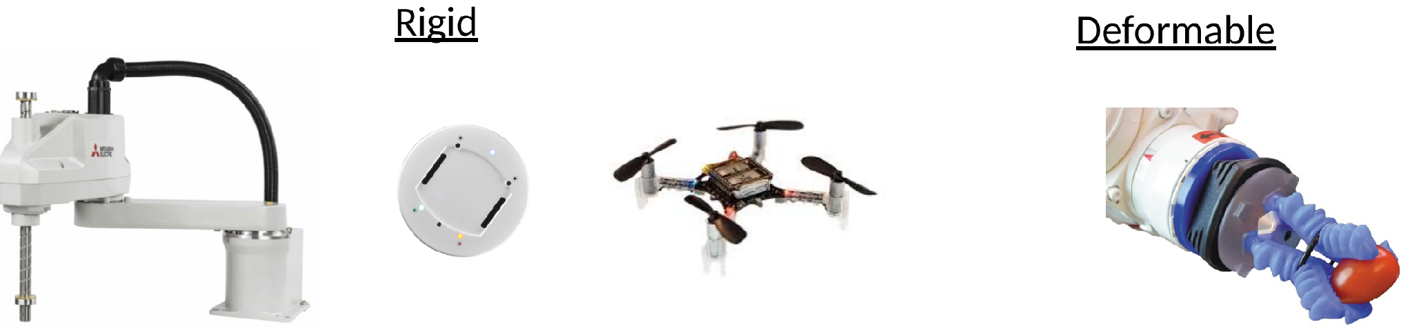
● Robots with rigid components under rotational and/or translational motion
● The position of any point on each body, in its attached frame, is fixed
EECE 5550 Mobile Robotics
8
Rigid motion
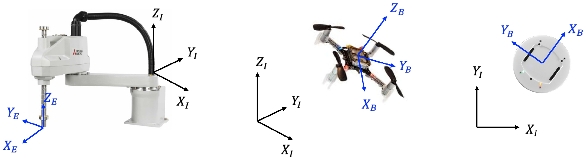
● Actuators, for example motors, apply force or torque to induce motion
● The position and orientation of the body frame, the pose, changes as a result
EECE 5550 Mobile Robotics
9
Kinematics or Dynamics
How is the pose influenced by the actuators?
● Kinematics: Geometry of motion. Ignores forces/torques.
● Dynamics: Physics of motion. Relates motion to forces/torques.
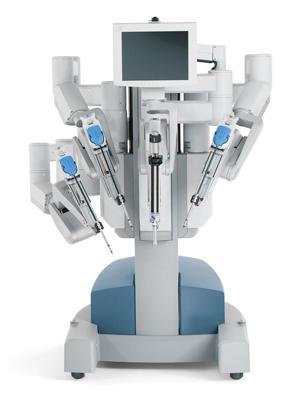
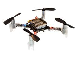
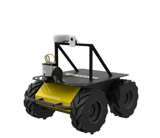
Choosing the model
Kinematic model: velocities, first-order ODEs
Dynamic model: accelerations, second-order ODEs. More accurate but more complex.
The decision depends on inertia, abrupt motion, and required precision.
EECE 5550 Mobile Robotics
10
When kinematics is not enough
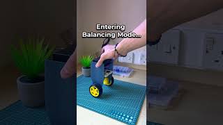
A balancing robot is a counterexample.
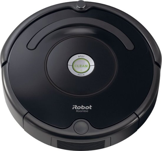
A TurtleBot
● Stable whether or not you model it
● Stop commanding it and it stays put
● Geometry predicts where it goes
● A kinematic model is sufficient
A balancing robot
● Falls over if you do nothing
● Stop commanding it and it hits the floor
● Geometry says nothing about falling
● Needs a dynamic model, and a controller
Same wheels, same motors, same encoders. Different model, because the physics matters.
EECE 5550 Mobile Robotics
11
Single integrator
A point that moves in whatever direction you ask. No heading, no constraints.
●State: position
○Orientation does not matter since the robot is assumed to move freely in any direction
●Control Input: velocity
Which kind of robot does it look like? Link
EECE 5550 Mobile Robotics
12
●Too simplified for most robots, but very useful for high-level planning and control
○where should the robot go?
○Design the inputs for single integrators first, then add the real complexity
Single integrator
First-order, discrete-time approximation
Sliding right is not possible, but there is a way to go there.
EECE 5550 Mobile Robotics
13
Double integrator
Now the input is acceleration, and velocity becomes part of the state.
State: position , velocity
Control input: acceleration
EECE 5550 Mobile Robotics
14
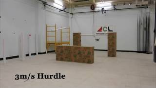
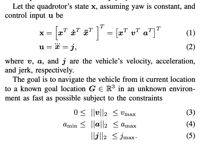
Triple integrator planning
for aggressive 3D collision avoidance
Lopez & How, “Aggressive 3-D Collision Avoidance for High-Speed Navigation”, ICRA 2017
EECE 5550 Mobile Robotics
15
Why this is the wrong model for TurtleBot 4
An integrator can move in any direction from rest. A TurtleBot cannot.
Single integrator
any direction, instantly
no heading in the state at all
TurtleBot 4
forward and turn only
heading is in the state, and it constrains motion
Everything from here on is about that one difference.
EECE 5550 Mobile Robotics

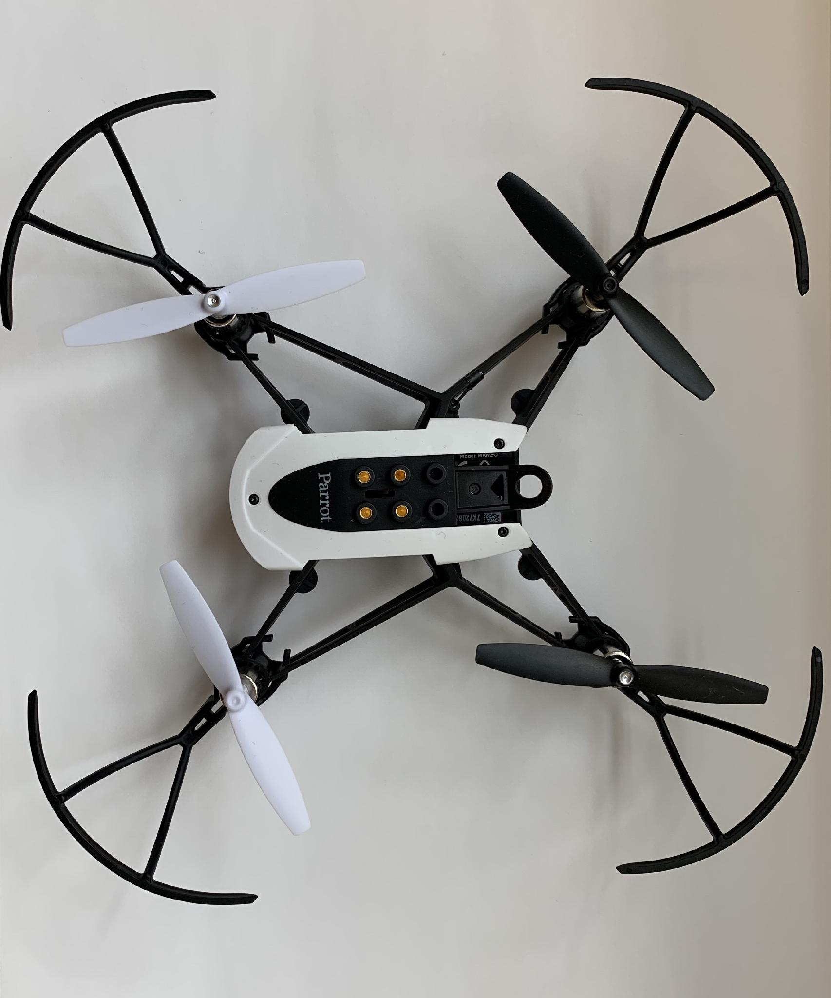
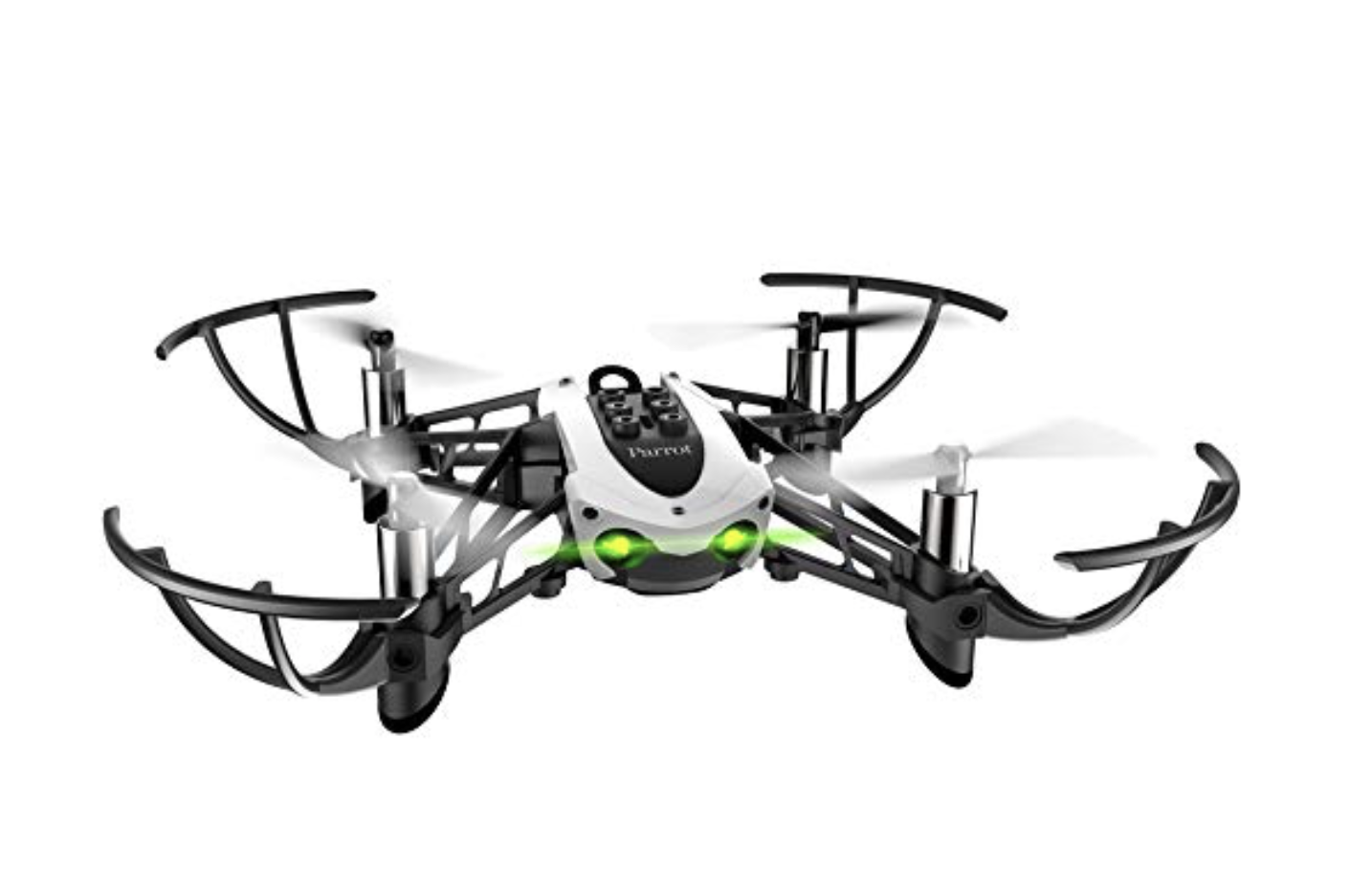
•A helicopter with four rotors
•Rotors are (often) placed
•in square formation
Quadrotor
16
EECE 5550 Mobile Robotics

•A helicopter with four rotors
•Rotors are (often) placed
•in square formation
•equal distance from the center of mass
Center of mass
Quadrotor
16
EECE 5550 Mobile Robotics

•A helicopter with four rotors
•Rotors are (often) placed
•in square formation
•equal distance from the center of mass
•Controlled by adjusting the angular velocity
Quadrotor
16
EECE 5550 Mobile Robotics

•A helicopter with four rotors
•Rotors are (often) placed
•in square formation
•equal distance from the center of mass
•Controlled by adjusting the angular velocity
T1
T2
T3
T4
Quadrotor
16
EECE 5550 Mobile Robotics

Increase the angular velocity
Thrust generation
Quadrotor
17
EECE 5550 Mobile Robotics


Increase the angular velocity
Thrust generation
Quadrotor
17
EECE 5550 Mobile Robotics


Quadrotor
Imbalance in left/right thrust generation
?
17
EECE 5550 Mobile Robotics


Quadrotor
Imbalance in left/right thrust generation
Roll
17
EECE 5550 Mobile Robotics


Quadrotor
Imbalance in front/rear thrust generation
?
17
EECE 5550 Mobile Robotics


Imbalance in front/rear thrust generation
Pitch
Quadrotor
17
EECE 5550 Mobile Robotics


Imbalance in ??? generation
?
Quadrotor
17
EECE 5550 Mobile Robotics


Imbalance in angular momentum generation
Yaw
Quadrotor
17
EECE 5550 Mobile Robotics

T1
T2
T3
T4
I.C.
A simple model for altitude dynamics
Question: Double-integrator or Triple-integrator?
18
EECE 5550 Mobile Robotics
19
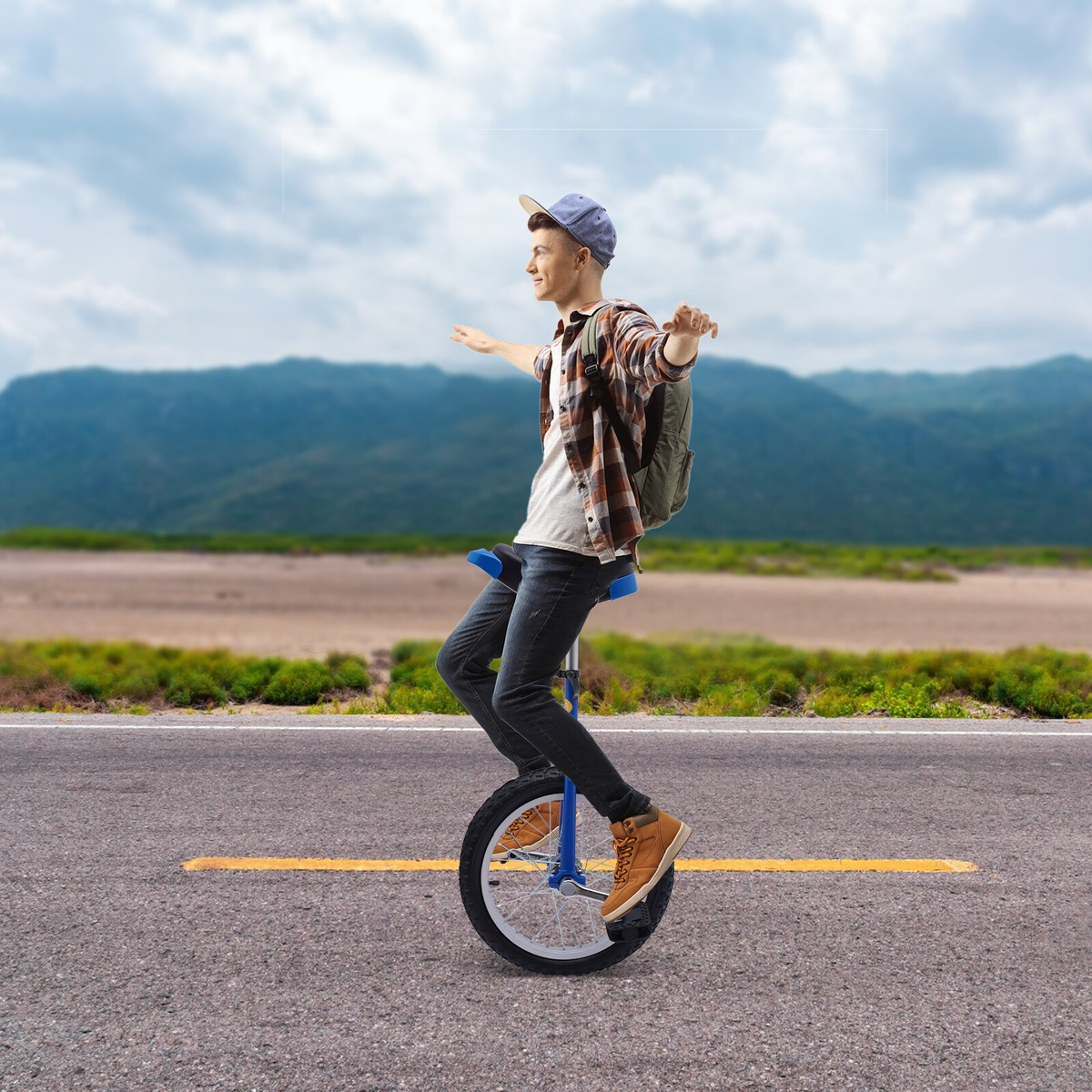
Unicycle
A simple but reasonable model for many mobile robots
Unlike the single integrator, the heading matters
●Output: pose (x, y, θ)
●Input: linear speed v and angular speed ω
EECE 5550 Mobile Robotics
20
Unicycle
A simple but reasonable model for many mobile robots
Unlike the single integrator, the heading matters
●Output: pose (x, y, θ)
●Input: linear speed v and angular speed ω

Two inputs on the right. Three state derivatives on the left.
EECE 5550 Mobile Robotics
21
Kinematics of wheeled vehicles
LOTS of different designs are possible for wheeled robots.
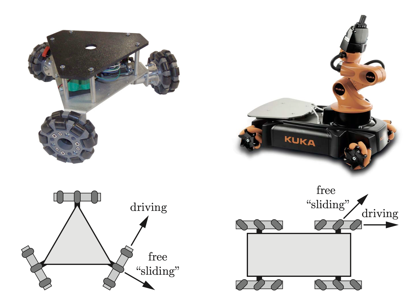
Examples:
●Bicycle model
●Differential drive, two or three wheels
●Ackermann steering, as in a car
EECE 5550 Mobile Robotics
21
Kinematics of wheeled vehicles
LOTS of different designs are possible for wheeled robots.

EECE 5550 Mobile Robotics
21
Kinematics of wheeled vehicles
LOTS of different designs are possible for wheeled robots.
Examples:
●Bicycle model
●Differential drive, two or three wheels
●Ackermann steering, as in a car
Main question: how does wheel geometry relate to robot motion (i.e. kinematics)?
EECE 5550 Mobile Robotics
22
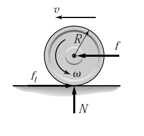
Rolling without slipping
Main assumption: all wheels rotate without slipping.
Key observation
These conditions correspond to constraints on possible robot motion.
●The contact point has zero velocity relative to the ground
●Wheel rotation and robot motion are locked together
●slip_status exists because this assumption fails sometimes
r
φ
v
v
EECE 5550 Mobile Robotics
22
Rolling without slipping
Main assumption: all wheels rotate without slipping.
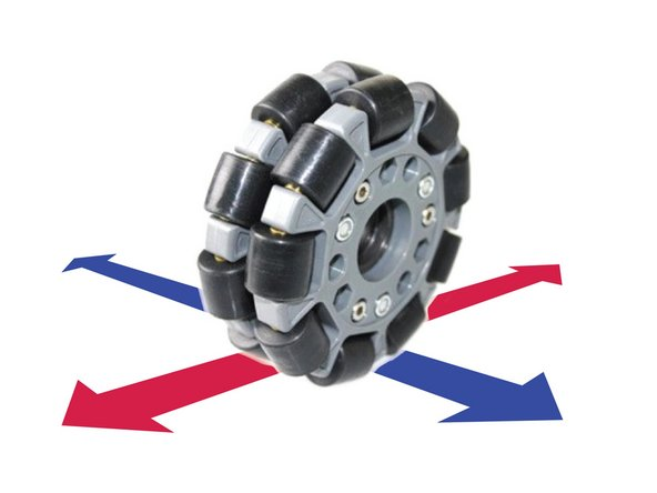
Question:
Does the "no-slip" assumption apply to omniwheels?
r
φ
v
v
Source: https://learn.browndoggadgets.com/Guide/Omni+Wheel+Robot/310
Forward velocity
No side-slip!
Lateral motion is prohibited
EECE 5550 Mobile Robotics
23
Wheel constraints on robot motion
For all wheels to roll without slipping, they must share one instantaneous center of curvature (ICC).
α
β
ICC
Differential drive, derived
Do the geometry in the robot’s own frame, where it is simple. Rotate into the world frame only at the end.
Four assumptions
- A1The robot is a rigid body on a flat floor.
- A2Each wheel rolls without slipping, so a wheel spinning at moves forward at .
- A3Nothing slips sideways: a wheel cannot move along its own axle.
- A4 is the midpoint of the axle, halfway between the wheels.
One point, one rate A1A3
A wheel can only roll forward or back, so it turns about a point on its axle line. Both wheels share that line and the body is rigid, so the whole robot turns about one point on it: the ICC.
Every point of a rigid body turns at the same rate .
Arcs over a short time
A point at distance from the ICC travels . The left wheel is the nearer one:
Divide each arc by
Arc length per unit time is the speed along the arc:
Rolling without slipping A2
Subtract (3) from (4): the terms cancel
Add (3) and (4), then use (6)
The center moves at the average wheel speed A4
It moves along only A3
The center turns about the ICC, so it moves at right angles to the axle. It never slides sideways:
Collected, in the body frame
Rotate the body velocity by , as in Lecture 2
The unicycle equations, now derived
The constraint, in world coordinates
points along in the world frame, so (9) becomes
Check it against motions you can picture
| Motion | Wheels | R | ||
|---|---|---|---|---|
| Straight line | ||||
| Spin in place | ||||
| Pivot | ||||
| Left turn | ||||
| Right turn | any |
, ,
EECE 5550 Mobile Robotics
25
Forward kinematics, collected
Wheel angular speeds in, pose derivative out.
body frame
world frame
is the wheel radius, the wheel separation, the wheel angular speeds.
You measure and yourselves in Lab 1. The published values and TurtleBot 4's values differ, and that difference is the systematic part of the odometry error.
EECE 5550 Mobile Robotics
26
Inverse kinematics
You publish v and ω. Something has to turn that into two wheel speeds.
invert the forward model
● This happens inside the Create 3, in firmware
● You never write it for this robot, which is why it is easy to forget it exists
● But every clamp, every saturation, and every wheel slip happens here
● And it is the first thing to check when the robot turns the wrong way
EECE 5550 Mobile Robotics
27
Verify on your TurtleBot
Exercise #2: find the ICC
DriveDistance, DriveArc, and RotateAngle
If those are not listed, check the hidden namespace:
What to take away
A model keeps what matters for the task and leaves out the rest. Kinematics is enough for a TurtleBot; a balancing robot needs dynamics and a controller.
A single integrator moves in any direction: . Good for planning, but wrong for a robot that cannot move sideways.
, , . Two inputs, three states, and the constraint : no sideways motion.
A wheel moves forward at and never along its axle. For every wheel to roll, all of them must turn about one point, the ICC.
and . Rotate the body velocity by and the unicycle equations follow.
and run in the Create 3 firmware. Measure and yourself: errors in them are the systematic part of odometry error.